
Products
We are a leading manufacturer of quality internal and external lighting products for commercial, industrial and retail applications.
View all productsProduct Types
Applications
At Ansell Lighting we design and manufacture an extensive range of luminaires for a diverse number of applications. Whatever the shape, purpose or style of your space, we have a lighting solution.
View all applicationsApplication Types
About
We are a leading manufacturer of quality internal and external lighting products for commercial, industrial and retail applications.
About overviewMore about us
Contact
We are here to answer any questions you may have, help you find a stockist or speak to a local member of our team.
Find out more
OCTO
OCTO delivers the complete smart lighting package to transform the efficiency and ambience of commercial and residential spaces.
OCTO overviewMore OCTO
Downloads
View and download our product catalogues, brochures and application guides. You can also search and download product datasheets, photometric and instructions.
Downloads available
Dimming – Digital Addressable Lighting Interface – (DALI) – (DD3)

DALI stands for “Digital Addressable Lighting Interface” and is an interface protocol for digital communication between electronic operating devices for lighting technology. In looking to look at the components of the name, DALI, one view is that they correspond as being, ‘D’ is for Digital, which is working in bits with the ability to process information, ‘A’ is for Addressable, which is the unique identity and operation, ‘L’ is for Lighting, which is the technology being driven, specifically LED technology and finally ‘I’ is for Interface, which is a way of interaction.
DALI (Digital Addressable Lighting Interface) is a two-way communication system that brings digital technology to lighting and is an international standard for communication, where DALI defines the commands that ballasts need to recognise in order to be considered DALI ballasts. The system allows individual ballasts to “talk” to the user and allows the user to “talk” back via DALI controllers, computers equipped with appropriate software, or building management systems (BMS). DALI sends messages around, and just like computer networks, those messages are picked up by the ballasts via addresses and the ballast with that address picks it up and follows the instruction given.
It has a simplified installation power lines and control lines can be laid together in the same cable, where the wiring may be in series, in a star arrangement or in mixed form. There is no need to consider the system polarity (+/-) of the DALI control line and it has a stable dimming function with all luminaires receiving interference-free digital signal and therefore the same dimmer value.
In looking at the DALI system, there are basically four main components required for a DALI circuit, that of the DALI controller or gateway, the DALI Bus Power Supply, some type(s) of DALI drivers installed into the lighting luminaires and an appropriate cabling system.
A DALI system has the ability to easily reconfigure lighting without the need for electrical installation work, making the process of commercial refurbishment or rearrangement, with regard to the staff and furniture much easier, as there is no need to re-route the control wiring to the fixtures. There is also the ability to reconfigure the DALI fixture by programming it to accept commands for a new control group or scene as opposed to a previous one, all of which is done via software instead of getting your hands dirty undertaking hard-wire changes. There is also the ability for lighting to be modified, either individually or across the entire facility, to accommodate the peak demand, the amount of visible daylight, and the energy costs., as well as allowing for an open protocol which accommodates the involvement of many different companies to co-exist on a DALI network making sure our products are all interoperable.
There are a number of parameters and values associated with a DALI network system:
- There is no polarity, in that the polarity of +/- of the DALI control line does not have to be minded.
- DALI voltage is 12.0 Volts to 20.5 Volts, but is typically set at 16 Volts DC, Non SELV.
- DALI system current maximum is 250 mA, dependent upon installed DALI power supply.
- Maximum count of DALI Operating Devices per DALI line is 64.
- Maximum count of DALI Groups is 16.
- Maximum count of DALI Scenes is 16.
- Data transfer speed is 1,200 bits/second.
- Maximum cable length of DALI wiring is 300 metres for a wire-cross-sectional area of 1.5 mm2.
- A DALI power supply is always required for each DALI line.
- The voltage drop across the DALI control line shall not be over 2 Volts.
- Resistance must always be 10 Ohms
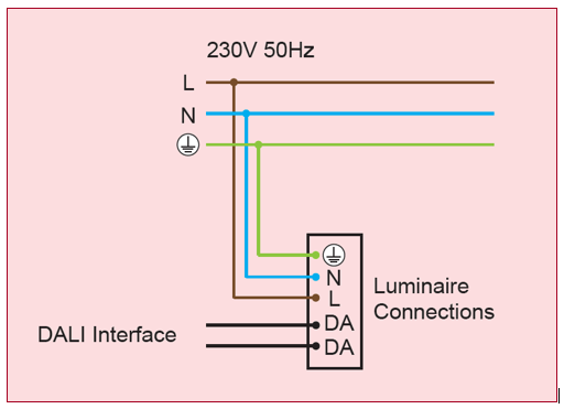
The installation of the DALI system takes place with customary installation material for mains voltage and for the DALI control circuit, 2 cables are required. The mains voltage and bus line can be led in the same cable. A cable which has 6 cores of Live, Neutral, Earth, Permanent Live (Emergency use), DALI Control 1, DALI Control 2 in 1.5mm2 can be used.
There are several wiring arrangements available to the installer for the wiring of a DALI system, being Bus wiring, Star wiring, Tree wiring and Line wiring, and there are several wiring arrangements which are not suitable, that of Ring wiring, Mesh wiring, Full mesh wiring &Mixed wiring.
DALI is protected against polarity reversal. DALI does not need any control unit as all information like scene values or group assignments are saved in the operating device and furthermore, DALI is event driven, which means that without a command there is no reaction and without a specific query the user will get no feedback.
There are a number of required components to have a working DALI system, where the driver which stores the memory and accepts DALI Commands, the Loop Controller or Bus Master provides power to the DALI buss and acts as a protocol translator with one required for every 64 DALI ballasts, and the control devices based upon the application and desired control as without control, the devices and lighting will operate at 100% light level
There are also a number of optional control devices, group controls, which may include occupancy sensors, PIR’s or demand controllers with a typical action of “Group to Light Level”, scene controls which can be represented by multi-button wall switches with a typical control of “Group A to Level / Group B off”, relay modules which accept commands for the ON/OFF control from a DALI system as well as typical applications for non-DALI items such as AV Equipment, Electric Blinds, etc.
With regard to the DALI Protocol of light source response, DALI utilises a precise dimming curve which is logarithmic, where the dimming curve is matched to the sensitivity of the eye. The range of operation for LED light sources is given as 0-100%, with 254 steps increasing at 2.8% per step.
You Might Also Be Interested In...

Dimming – Digital Serial Interface (DSI) – (DD2)
Subscribe to our newsletter
Get monthly news, tips, and new product updates delivered straight to your inbox.
Email addresses are never sold or given out to anybody. By subscribing, you agree to our Privacy Policy and Terms.